Deep Image Comparison#
When a Slider Layout consists of deep images, you will have to explicitly turn on the property deep_image_comparison to enable this feature. If not, they will be treated like normal images. Also, if any image in the set is not a deep image, deep_image_comparison will be automatically disabled.
Look at the images below. Initially, what you see is a simple image with a combination of RGB colors. The Probe and Pin will show the RGB values, just like the previous example.
Because the image is enhanced, as each image is loaded, the variables available in each image are added to the drop-down menu.
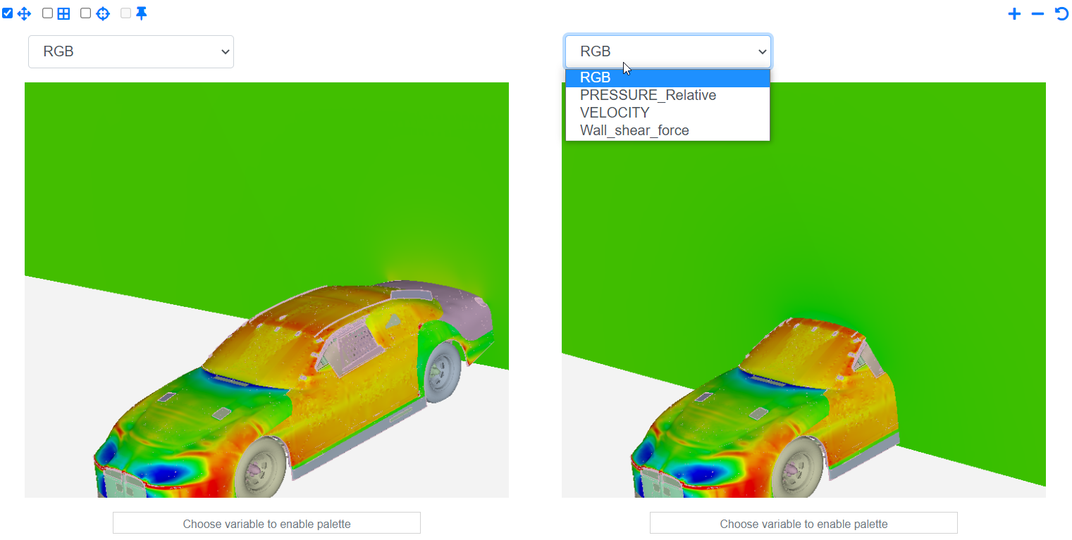
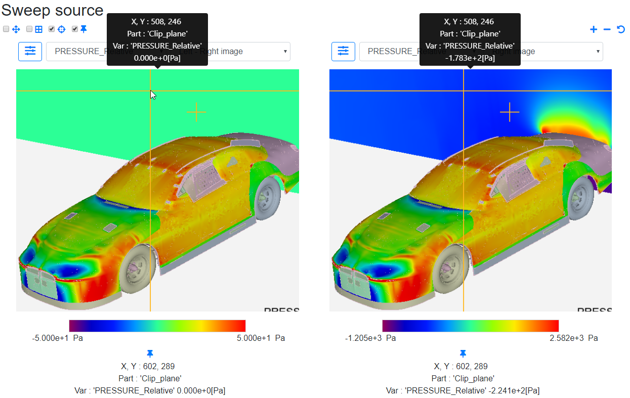
When a variable is selected, all parts that contain the selected variable are shaded. In the example below, the clip plane which contains PRESSURE_Relative is fully shaded in gray scale. The color or intensity of shading is based on the value of PRESSURE_Relative which may vary from region to region. The current mapping of the shading color to the value is displayed in the palette bar below the image. If a variable or any part that contains the variable is not displayed in the image, you will see a warning.
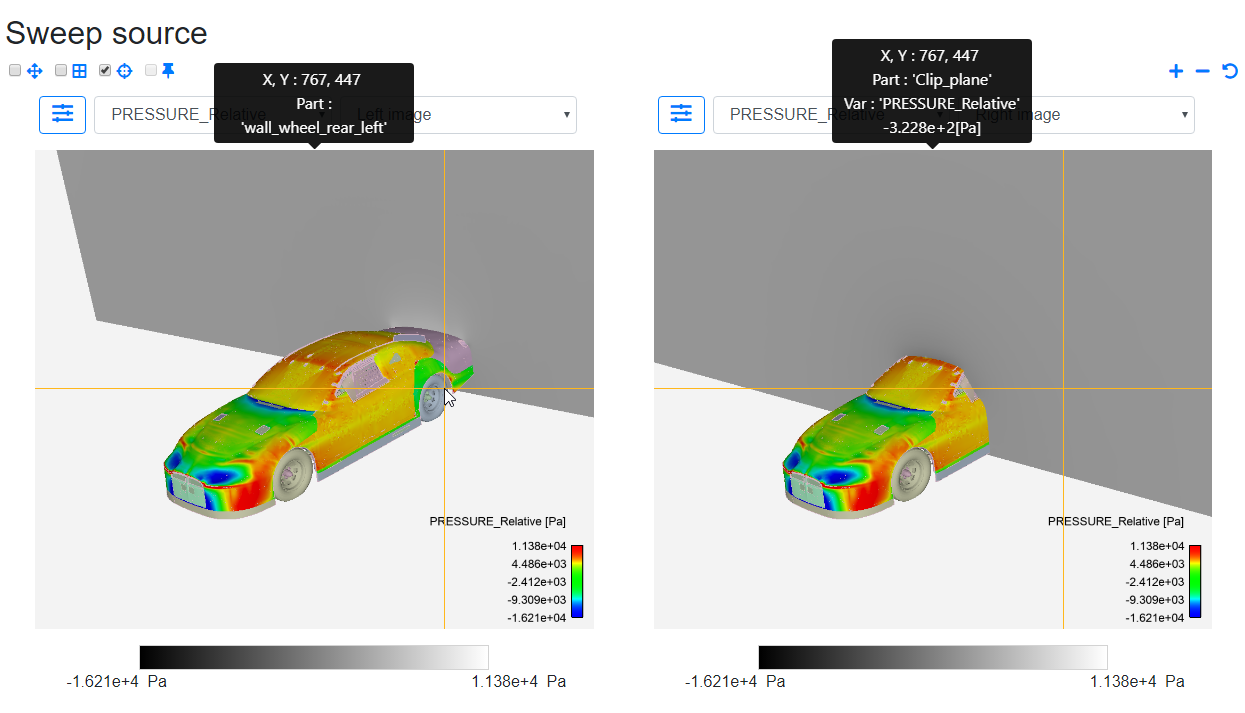
Use Probe to view the value at each point. Previously when the RGB option was selected in the drop-down, the RGB values were displayed. Now that a variable is selected, the variables are read from the enhanced image and then displayed, along with the values and the part associated with it as well. Each pixel's 'deep' information can be read this way.
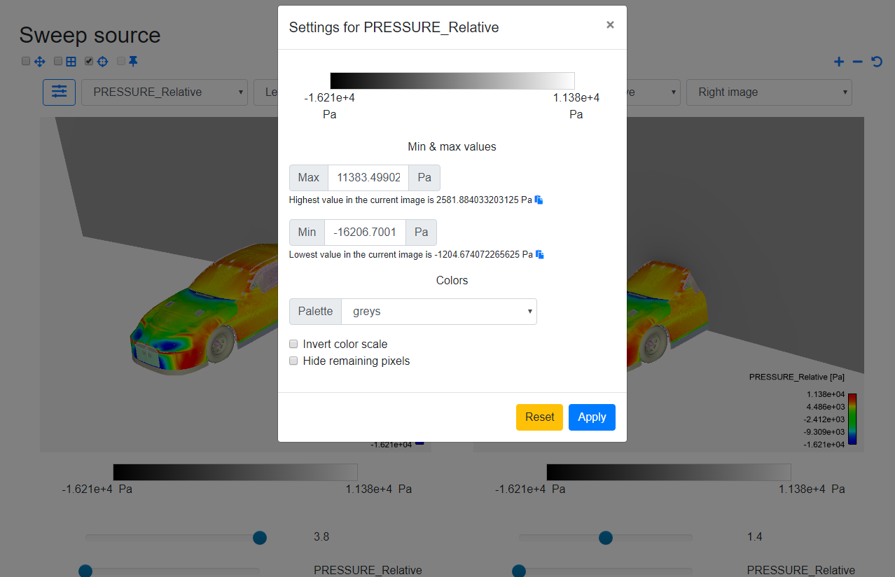
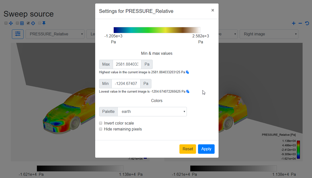
Let's consider the image on the left. Click on the settings icon on the left. A dialog will open up with the current settings. There are several things you can customize:
Min & Max
These values signify the range of colors or shading intensity that is used from the selected palette. In the example below, the grayscale palette ranges from -16206.70 Pa, which is the Min or minimum to 2581.884 Pa, which is the Max or maximum.
This means that parts with values less than the Min will be colored black and parts with values greater than the Max will be colored white and parts with all values in between the Min and Max values will be colored in decreasing intensity of black from Min to Max.
Their mapping is what is shown in the preview scale at the top. This preview should update as the settings are changed.
The default Min and Max values are taken from the current palette range selected in EnSight for that variable. If not available, they will be set to 0.
Below the input boxes for Min and Max are displayed the lowest and highest values for that variable in the entire image, respectively. You may use the copy icon next to it to populate the input boxes with those values.
You may also set your own values, but make sure the value is a valid number and Min is lesser than Max.
Color
A variety of palettes are available to select from the Palette drop-down. The default is grayscale, which is used along with the default Min-Max values to initially generate the image. Changing the palette should update the preview scale to give a feel of what the result would be.
The Invert color scale option is used to invert the color scale. For example, in the image below, you can invert the scale so that parts with values less than the Min will be colored white and parts with values greater than the Max will be colored black and parts with all values in between the Min and Max values will be colored in increasing intensity of black from Min to Max.
In order to hide all the pixels and to only keep the parts that contain the selected variable, check the Hide remaining pixels option. Be aware that when you probe, Probe will ignore the parts that are hidden and only display what is visible.
Once you click Apply, the settings should be saved and the image will be regenerated with the updated settings. To the right of the variable drop-down is a list of different views, which we will cover in detail later.
Settings are saved per variable, so that you don't have to set them again as you switch between variables. You may use the Reset button at any time to reset the settings back to defaults.
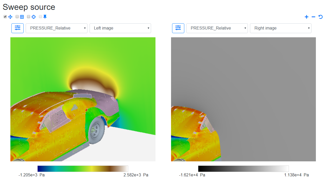
Consider the left image. Let's see what happens when the highest and lowest values are used as Max and Min respectively, and a different palette is chosen. Check the preview scale to see if everything looks good.
Click Apply. Now you'll see that the palette is updated and the image is regenerated. Let's zoom in for a better view.
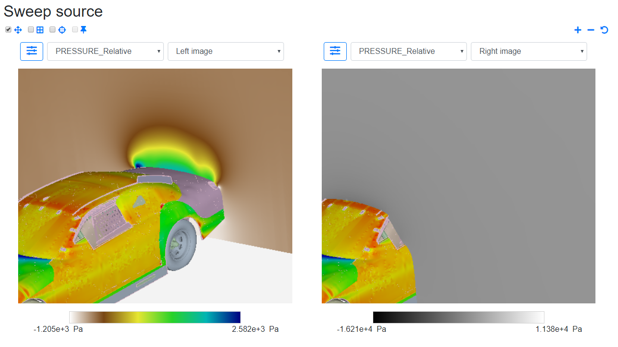
Let's invert the color scale of the left image now.
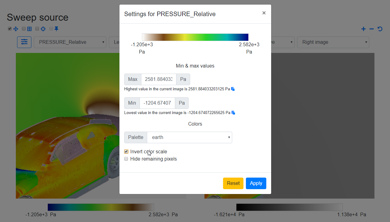
Check the preview scale. Click Apply. Now, you'll see the changes with the new scale applied.
Now let's try hiding the remaining pixels. Check the option in the settings dialog. You will see a Background option. This decides what the 'hidden' area will look like. This can be any value between 0 (full white) and 1 (full black).
Let's switch to the same image on the right and let's try a different background for the right image with similar color and min-max settings.
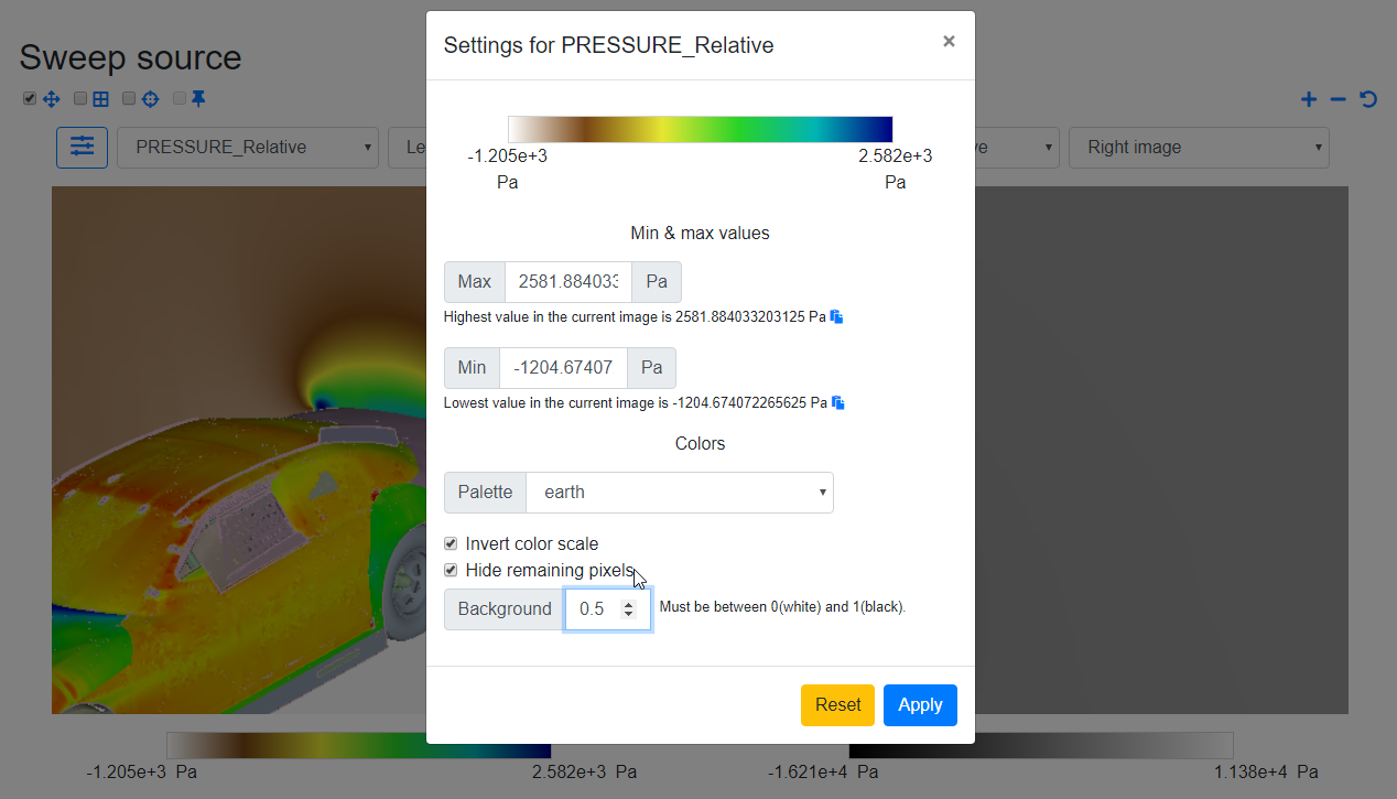
Click Apply. Notice that the other parts that do not contain the selected variable are now replaced with the selected background. The left image has a background of 0 and the right has a background of 0.5. Everything else except the clip plane is now hidden.
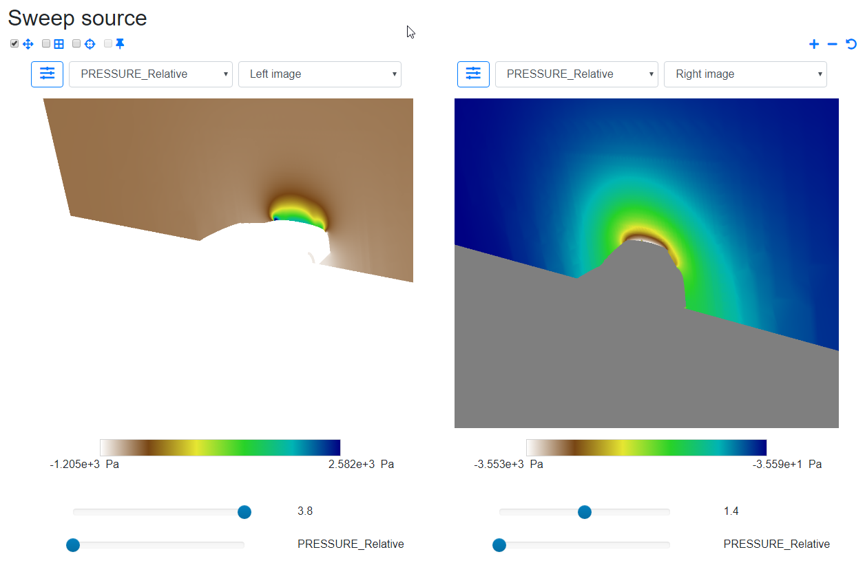
Note that all the features mentioned above apply to both right and left images. Let's un-check the hiding option on both sides.
Deep Image Differences#
Now look at the second drop-down considering the left image again. This is what we call a View. The default view is the current image which is 'Left image' and 'Right image' for images on the left and right respectively.
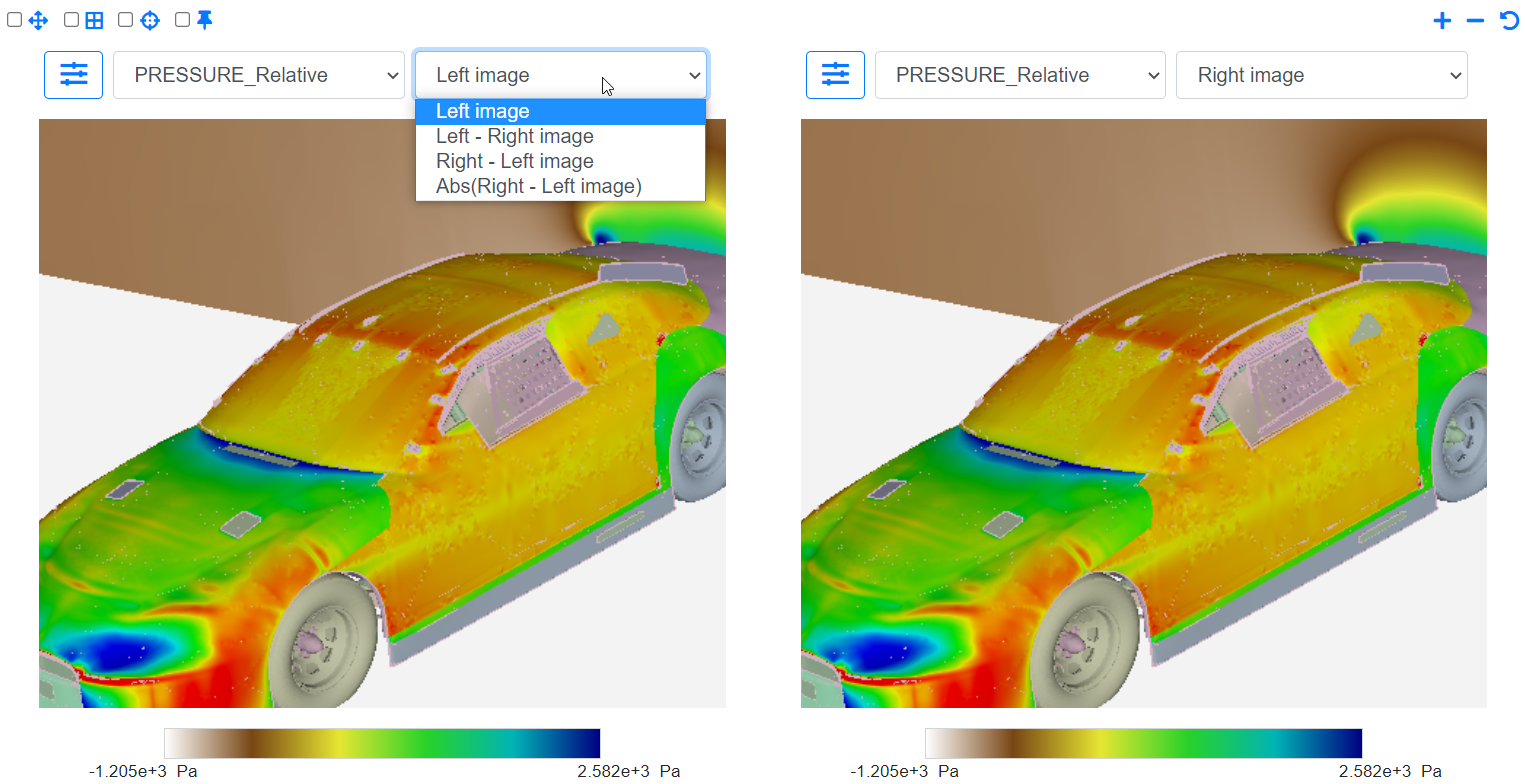
Let's look at the available views:
Left image : The current image.
Left - Right image : The computed image with values that are the difference between values on the left and values on the right image.
Right - Left image : The computed image with values that are the difference between values on the right and values on the left image.
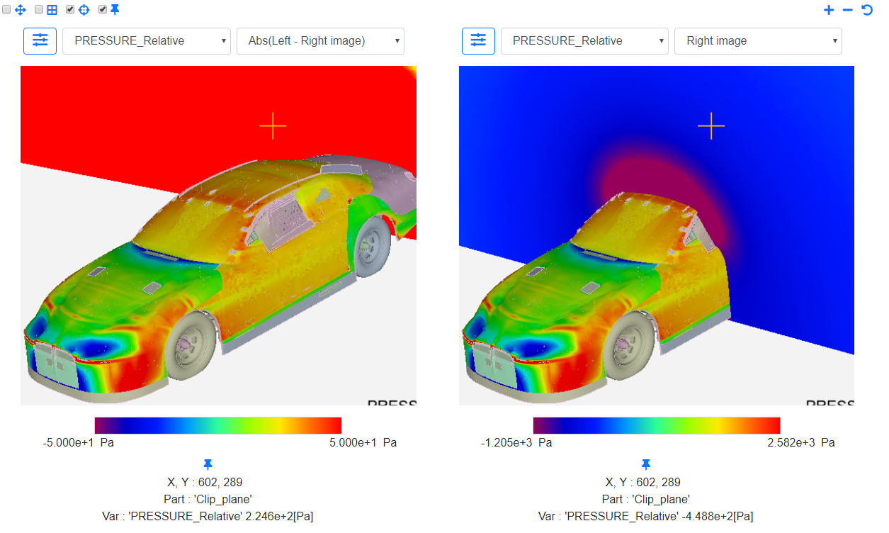
Abs(Right - Left image) : The computed image with values that are the absolute value of the difference between values on the left and values on the right image.
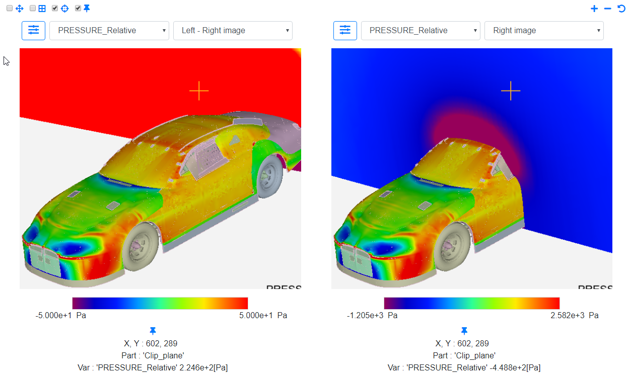
You may choose any view you like for any image, and the image next to whichever drop-down you're playing with will regenerate itself. Let's select Left - Right image. In order to see the palette apply properly, let's set the Min to -50 and Max to 50. Let's also try a different color palette.
Note that the highest and lowest values in the image are zero because both the images are the same and the difference in PRESSURE_Relative is zero.
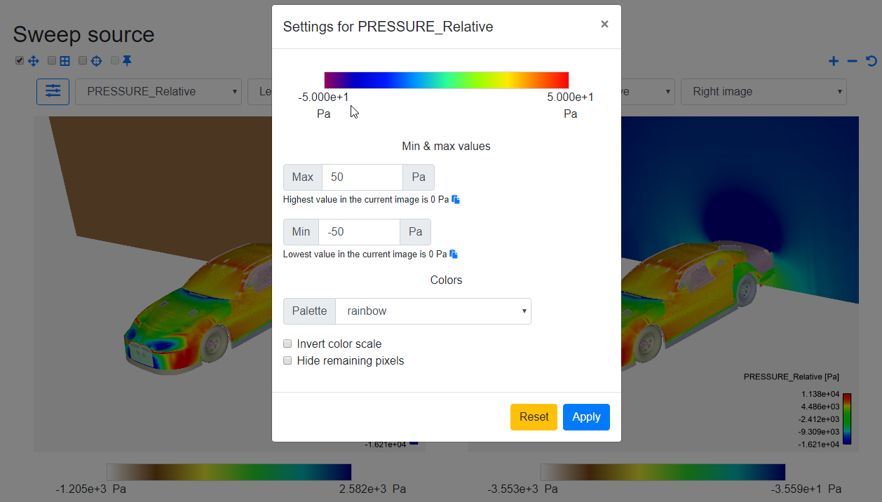
Hit Apply again. Since the images on both the left and right are the same, the difference must be zero. Notice that the clip plane is shaded by a color, which, if you look at closely, matches the color at the center of the color scale, which is zero. This is how it works. Let's also verify with the Probe and Pin. These will read as 0.
Here's another example of the Left - Right image view, but with a different image. Hence, the difference values will be non-zero. Let's try changing the image on the right. When there is a change in image, the computation is run again with the new image. Notice that the Pin updated its value and the clip plane's shade was updated as well to reflect the change.
Now, switch over to the Right - Left image view. This is the opposite of the previous Left - Right image view. For example, if the computed difference value for PRESSURE_Relative in the Left - Right image view was 50 Pa, the corresponding value in the Right - Left image view would be -50 Pa.
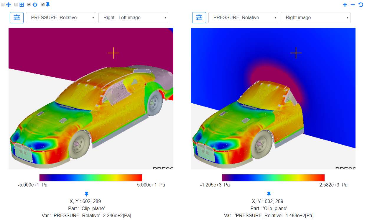
The Abs(Right - Left image) view is also very similar. The only difference is that the computed values for the chosen variable are calculated as the absolute value of the difference between the value in the right image and the left image. For example, if the computed difference value for PRESSURE_Relative in the Right - Left image view was -50 Pa, the corresponding value in the Abs(Right - Left image) view would be 50 Pa.